Magnetic Field Due to A Current
Flashcards for topic Magnetic Field Due to A Current
Preview Cards
Front
Derive the expression for the magnetic field at a distance from a long, straight current-carrying wire using Ampere's Law.
Back
Using Ampere's Law:
- Draw a circular path of radius around the wire
- The magnetic field is tangential to this path with constant magnitude
- The circulation is:
- The current enclosed by the path is
- By Ampere's Law:
- Therefore:
- Solving for :
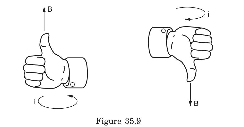
The direction follows from the right-hand rule: grip the wire with your right hand with thumb pointing along current direction; your fingers curl in the direction of the magnetic field.
Front
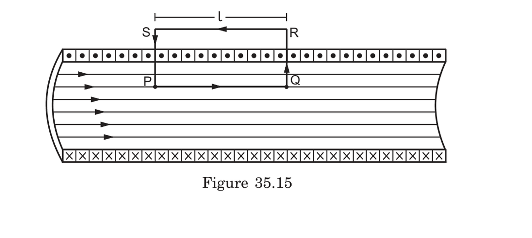
Given a solenoid with turns per unit length carrying current , derive the expression for the magnetic field inside the solenoid using Ampere's Law.
Back
Derivation using Ampere's Law:
-
Draw a rectangular path PQRS with:
- Side PQ parallel to the solenoid axis inside the solenoid
- Side RS outside the solenoid
- Sides QR and SP perpendicular to the solenoid axis
-
Calculate circulation:
- Along PQ: (where is length of PQ)
- Along QR, RS, SP: (B is either zero outside or perpendicular to )
- Total circulation:
-
Current enclosed by path:
- Number of turns enclosed =
- Total current =
-
Apply Ampere's Law:
-
Solving for B:
Note: This is valid for infinite solenoids. For practical applications, the approximation works well when the solenoid length is at least 5-6 times its diameter.
Front
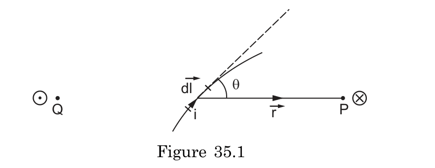
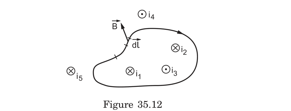
When applying the Biot-Savart Law to various current configurations, how do you determine whether the magnetic field at a point goes into the plane or comes out of the plane?
Back
To determine if the magnetic field goes into or out of a plane:
-
Identify the direction of current (i) and the position vector (r) from the current element to the point
-
Apply the right-hand rule to the cross product (dl × r):
- Place your right hand along the current direction dl
- Curl your fingers toward the position vector r
- Your thumb points in the direction of the magnetic field
-
Conventional notation:
- ⊗ (encircled cross) indicates field going into the plane
- ⊙ (encircled dot) indicates field coming out of the plane
Example: For a straight current-carrying wire in a plane with current flowing upward, points to the left of the wire experience a magnetic field going into the plane, while points to the right experience a field coming out of the plane.
Front
If two parallel wires carry currents in the same direction, what forces do they experience and why? How does this relate to the magnetic field pattern around each wire?
Back
When two parallel wires carry currents in the same direction:
-
They attract each other with a force per unit length given by: Where d is the separation distance between wires.
-
The physical explanation:
- Each wire produces circular magnetic field lines
- Wire 1 experiences a force due to being in Wire 2's magnetic field
- Wire 2 experiences a force due to being in Wire 1's magnetic field
- When currents flow in the same direction, each wire sits in a region where the other's field lines are oriented to produce an attractive force
-
This principle forms the basis for defining the ampere: two parallel wires 1m apart carrying 1A each experience a force of 2 × 10⁻⁷ N per meter.
If the currents flow in opposite directions, the wires would repel each other with the same magnitude of force.
Front
How can you apply the right-hand rule to determine the magnetic dipole moment of a current-carrying loop, and what is its mathematical representation?
Back
To determine the magnetic dipole moment of a current-carrying loop:
- Curl your right-hand fingers in the direction of the current flow
- Your extended thumb points in the direction of the magnetic dipole moment vector
Mathematical representation:
- The magnetic dipole moment vector is given by:
- Where is the current and is the area vector perpendicular to the loop
Properties:
- The magnetic dipole moment has units of A⋅m²
- Its direction is perpendicular to the plane of the loop
- The strength is proportional to both current and loop area
- For multiple turns N:
Example: A 5 cm radius loop carrying 2A current in counterclockwise direction (when viewed from above) has a magnetic dipole moment of A⋅m² pointing upward.
Front
When a circular current loop is placed in an external magnetic field, what determines the torque experienced by the loop, and how is this related to the right-hand rule?
Back
The torque experienced by a current loop in an external magnetic field:
- Is given by: where is the magnetic dipole moment
- Has magnitude: where is the angle between and
- Is maximum when the dipole moment is perpendicular to the field ()
- Is zero when the dipole moment is parallel or antiparallel to the field ( or )
Right-hand rule connection:
- The dipole moment direction (from right-hand thumb rule) determines how the loop orients in the field
- The loop experiences torque that tends to align its dipole moment parallel to the external field
- The torque direction follows the right-hand rule for cross products
Example: A circular coil with its dipole moment at 30° to a 0.5T magnetic field will experience a torque that rotates it toward alignment with the field lines.
Front
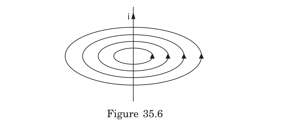
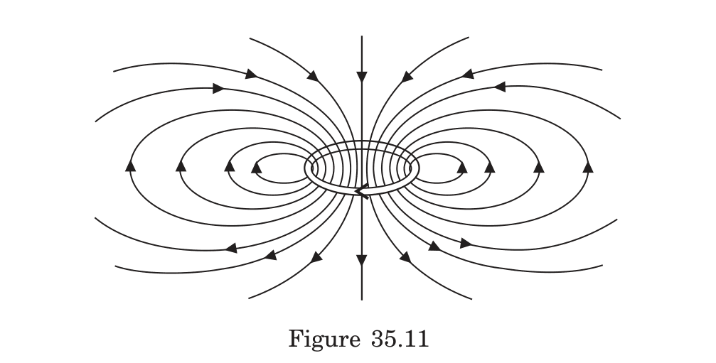
What is the pattern of magnetic field lines produced by a circular current loop, and how does this pattern relate to a bar magnet?
Back
The magnetic field lines of a circular current loop:
- Form closed loops that emerge from one face, curve around the outside, and enter through the opposite face
- Are densely packed and roughly parallel inside the loop (stronger field)
- Become less dense as distance from the loop increases (weaker field)
- Are symmetrical about the axis of the loop
- On the axis, point in one direction through the loop and in the opposite direction outside the loop
This pattern is identical to that of a short bar magnet or magnetic dipole, with one face acting as a north pole and the opposite face as a south pole.
Example: A compass needle placed at various positions around the loop will align tangentially to these field lines, always pointing from north to south.
Front
What specific notation convention is used to represent current direction perpendicular to a plane, and how does it relate to vector field visualization?
Back
The notation convention for current direction perpendicular to a plane:
-
Current coming OUT of the plane: Represented by a dot (⊙)
- Mnemonic: Visualize the tip of an arrow pointing toward you
- Represents positive z-direction in standard right-handed coordinates
-
Current going INTO the plane: Represented by a cross (⊗)
- Mnemonic: Visualize the fletching (feathers) of an arrow moving away from you
- Represents negative z-direction in standard right-handed coordinates
This notation is used consistently in vector field visualization for any vector pointing perpendicular to the plane (including magnetic fields, electric fields, angular momentum, etc.).
The convention complements the representation of vectors lying within the plane, which are shown as arrows pointing in their respective directions, forming a complete system for visualizing 3D vector fields on a 2D surface.
Front
How does Ampere's Law apply to finding the magnetic field inside a solenoid, and what path should be chosen to simplify the calculation?
Back
To apply Ampere's Law to a solenoid:
-
Choose a rectangular path with:
- One side parallel to the solenoid axis inside the solenoid
- One side outside the solenoid
- Two sides perpendicular to the axis
-
Calculate circulation:
-
For this path:
- Only the side inside contributes to the integral (B·dl = Bl)
- Other sides contribute zero (B perpendicular to dl or B = 0)
-
The enclosed current is: (where n = turns per unit length, l = length of path, i = current)
-
Thus: , giving:
This uniform field exists only inside a long solenoid and points along the axis direction.
Front
How does the right-hand rule apply to determining magnetic field direction in circular current loops and solenoids, and what are the field characteristics in these configurations?
Back
Right-Hand Rule for Magnetic Fields
Single Circular Loop
- Right-hand thumb rule:
- Curl fingers of right hand in direction of current flow
- Extended thumb points in direction of magnetic field through loop center
- Field direction indicators:
- Counterclockwise current → field points toward viewer
- Clockwise current → field points away from viewer
- Field pattern:
- Lines emerge from one face (north pole)
- Loop around and enter opposite face (south pole)
- Strongest at center, weaker with distance
Solenoid (Multiple Loops)
- Field characteristics:
- Adjacent loops with same current direction create reinforcing internal fields
- External fields from adjacent turns tend to cancel
- Field strength increases with more loops (proportional to number of turns)
- Field properties inside long solenoid:
- Nearly uniform field strength (B = μ₀ni)
- Parallel field lines
- Field strength depends on current (i), turn density (n)
- Overall pattern:
- Resembles bar magnet with north and south poles at ends
- Almost zero field outside a tightly wound solenoid
- Practical application: MRI machines utilize this principle for precise imaging
Showing 10 of 47 cards. Add this deck to your collection to see all cards.